Sizing Potable Water Lines (2010 NPC)
In order to provide a consistent supply of water to every fixture in a plumbing system the water lines must be sized according to a number of factors. Gone are the days of piping in a home using only 1/2″ copper, people today expect their water pressure to be consistent, regardless of the number of fixtures being used.
Sizing factors for Small Commercial Buildings
In order to properly size the potable water system, a number of factors must be taken into account:
- Building Type. Whether the building is residential or commercial will decide how the fixtures are used and therefore how they will be sized.
- Fixture units. Number and type of plumbing fixtures in the building. This is calculated in FU (fixture units), which is a standardized way to calculated the expected demand, each fixture having a numerical value given to it.
- Supply pressure. The supply pressure available from the water main will dictate the required size of the water service as well as the requirements of a pressure reducing valve (PRV).
- Longest run. Is the distance from the beginning of the water distribution system, to the most distant fixture. This will take into account friction loss in the piping and valves.
- Pressure losses. The elevation change from the service to the highest fixture must be calculated to find the pressure drop. Each meter of height drops the pressure 10kPa, or 1 foot = 0.433 PSI. Losses caused by water control equipment (treatment systems, pressure reducing valves, backflow preventers, etc.) are also combined and added to the pressure drop caused by elevation changes.
- Type of piping material. The maximum recommended velocity in M/S can be found from the pipe manufacturer’s specs. (increasing pipe size under the same demand reduces flow velocity)
- Plumbing codes for the area (for this article, the Canadian Plumbing Code will be used)
Sizing walkthrough
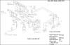 The best way to learn is to “see and do”, so print off this image (right click- Print target/save image), and get a 2010 NPC code book. (Unfortunately the code tables are not permitted to be reprinted here)
Step 1 – First, size all of the fixture supplies and fill in their fixture units in the spaces provided. To do this use Tables 2.6.3.2.A. , 2.6.3.2.B. , 2.6.3.2.C. , 2.6.3.2.D. (since this is a commercial building, the “public use” fixture units are used) Use the “Total Fixture Unit” Column when sizing.
| Fixture (Abbreviation) | Supply Size (Inches) | Fixture Unit Value (FU) | ||
| Lavatory 8.3LPM (Lav) | 3/8″ | 2 FU | ||
| Water closets with flush tank, 6 LPF (WC) | 3/8″ | 2.2 FU | ||
| Service Sink (SS) | 1/2″ | 3 FU | ||
| Kitchen Sink 8.3LPM (KS) | 1/2″ | 1.4 FU | ||
| Shower 9.5LPM | 1/2″ | 4 FU | ||
| Hose Bibb | 3/4″ | 6 FU Size using 2.6.3.2.D. |
||
| Laundry Tray (LT) | 1/2″ | 1.4 FU |
Step 2 – Using the given elevation of the highest fixture (8M) find the pressure loss in the system. For each Meter of elevation you lose 10 kPa. 442kPa – (8M x 10kPa) = 442kPa – 80 kPa = 382kPa. Using the available pressure of 382kPa you can now size the water distribution system using Table A-2.6.3.1.(2)A. on page A-66 of the appendix. With a run of 75M and a pressure of 382kPa you will use the table with a pressure range of 311-413kPa and the column 76M.
Step 3 – Starting from the most downstream fixture and working toward the water service, fill in the fixture unit values and pipe sizes. Remember if the pipe
only supplies one fixture to use the minimum supply table(2.6.3.2.A.) not the distribution table(A-2.6.3.1.(2)A.). For testing purposes always use the minimum size shown in the code book, even if you wouldn’t use it in real life (IE: 5/8″)
Step 4 – Sizing the service water heater supply is done by adding all of the hot water fixture units(HWFU). Fixtures that are supplied with both hot and cold water do not place any additional load on the cold water distribution, only add HWFU’s to the cold water distribution side that do not have a cold supply, such as a dishwasher(not applicable in this drawing).
Step 5 – The water service pipe can be sized in this example using the “pressure over 413 kPa” table.
.JPG) Now you should be able to size all potable water pipes in the system or any other light commercial system using the few tables covered here and a little math. Here is a completed drawing to check your answers against.
Now you should be able to size all potable water pipes in the system or any other light commercial system using the few tables covered here and a little math. Here is a completed drawing to check your answers against.