Making a plumbing sketch or pipe diagram is a necessary step in the design process. As residential building plans do not typically include plumbing diagrams a sketch will assist both the designer and provide important information to the one installing the plumbing.
Sketching basics
Sketches are simple line diagrams that are not intended to provide great amounts of detail, but simply place ideas into a graphical form. Sketches are not drawn to scale as with blueprints, but should be proportionate. The old saying “A picture is worth a thousand words” is completely true when talking about piping arrangements; just imagine trying to describe the intended location of pipes in three dimensions using only the written word.
As your sketches become more refined additional information should be added; such as pipe sizes, fixture location, dimensions and plumbing fittings until your confident that someone else would understand your sketch and be able to follow it’s design.
Types of plumbing sketches
There are two main types of plumbing sketches/drawings used by plumbers and mechanical designers to illustrate proposed plumbing layouts; which are, orthographic and isometric sketches.
Orthographic sketching
Orthographic sketching is best described as a two dimensional drawing shown from a vantage point. Building plans for example are illustrated as if someone was looking down on them(top view), this is called a plan view and best describes horizontal features; such as underground piping for example.
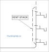 Another common orthographic view is a front view; also called an elevation view. An elevation view is from the perspective of a person standing in front of a structure and best describes vertical features; such as a plumbing stack.
Isometric sketching
An isometric sketch is a two dimensional drawing that creates the illusion of three dimensions using angular lines. This is the preferred drawing method for plumbers as it shows the most information about the piping layout.
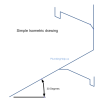 Although an isometric drawing is the most complex to draw, it has definite advantages; such as showing both horizontal and vertical piping on a single drawing. Making an isometric sketch is accomplished by imagining yourself at the lowest point(downstream) in a plumbing system and drawing it as you would see it; if it was laid out from lower left to upper right.
When drawing on paper, an angle of 30 degrees(or increments there of) is used to illustrate pipes running horizontally and vertical pipes are drawn straight up and down. The one problem with an isometric sketch arises when pipes are on angles  other than horizontal or vertical; such as 45 degree fittings. These “odd” angles are drawn as they would appear using 60 degree angles. When trying to draw circles in isometric drawings you will have to use an ellipse. A simple drawing tool called a triangle with the angles 30-60-90 will help you keep your drawing in the proper perspective. You can also purchase isometric graph paper or use printable graph paper.